I like my Grizzly 3616 Mill, mostly. One of the most anoying things was
the tri-handle quill feed. It was always getting in the way, and on
more than one occasion, I bent it cranking up the knee.
My machining mentor, Gordon Carlson, has a Bridgeport with a speed
handle. After using for a few months, I purchased one from Enco and
designed a replacement for the original tri-handle.
Below is the components of the original tri-handle (minus the spring).
The small handle on the right was used to draw the tapered end into a
mating taper in the qurill feed gear for use with the handle. Losen the
handle and the spring seperates the handle from the grar. The gear is
connected to the downfeed micrometer dial for precision downfeed.
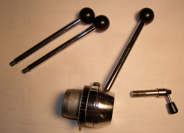
Original Parts
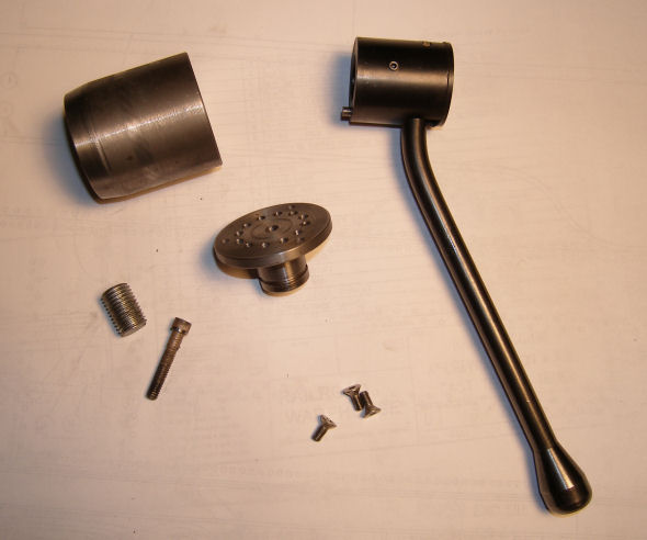
Here are the new parts. Clockwise from to left:
1. The spindle.
2. Purchased Speed Handle
3. 10-32 flat head, socket head screws
4. 1/4-20 1 1/2 socket head cap screw
5. The threaded end of a 16mm metric bolt, drilled and tapped 1/4-20 (to fit the mill's existing threads)
6 (center). Spindle front
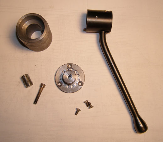
Here is another view of the same parts.
Below are the Drawings
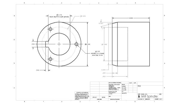
Click the for a larger version
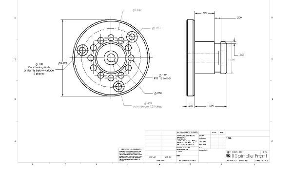
Click for a larger version
There is nothing fancy about the machining. Make sure the taper on the
Spindle part matches the downfeed grar and the bore is a neat slip fit.
I cut the keyway slot using a single point HHS tool on the lathe.
Feeding a small amount, 0.005, and cranking the carrage to the left for
each pass until the depth is reached. I had access to a keyway broach,
but none of the guides or the cutters were even close (English broach, metric keyway).
The countersinks in the Spindle Front should be deep enough so that the
flat head screws do not protrude into the Speed Handle. The 1 inch
protrusion for the speed handle should be a neat slip fit with the
handle you pruchased. The 12 index holes need to be accuratly located
to engage with the handle's locking pin. If they don't you may have to
open them up to a larger diameter, and that would make for a sloppy fit.
To hold the assembly on the mill spindle, I pruchased a 16mm bolt, cut
off 1 inch of the threaded portion, and drilled and taped through the
center with 1/4-20. The newly threaded bolt threads into the existing
spindle, slip the assembly over the spindle, aligning the key, and
instert the 14-20 cap head screw through the Spindle Front into the
16mm's 1/4-20 thread, and tighten.
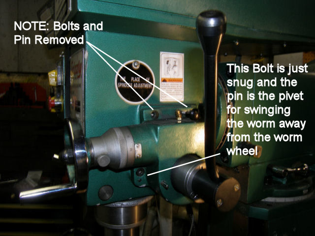
The downfeed handle needs some modification. I removed the two top
screws and the top guide pin. I use the bottom guide pin, with the
bottom screw just snug, to swing the downfeed worm up and out of the
way of the worm wheel. In this position, the Speed Handle can be used
to move the quill down.
To use the downfeed micrometer wheel, swing the gear housing down while
turning the downfeed wheel clockwise to engage the worm. At first, I
just
inserted the top taper pin to lock the gear housing in the proper
place. I have subsequently reamed the pin hole straight, and made
a pin assembly with a sping to puul it in, and a small handle to
pull it out. Pull the pin out to disengage the
gears. Swinging the gear housing down, the spring pin drops into the
hole.
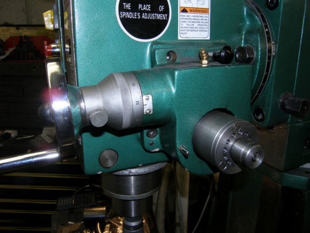
Below are photos of the assembly installed, one without the handle, and one with.
My Main Construction Page
Karl Kobel